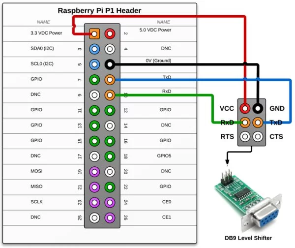
The following python program reads 10 characters from the serial port and sends back it. Import serial ser = serial.Serial ('/dev/ttyAMA0') #Open named port ser.baudrate = 9600 #Set baud rate to 9600 data = ser.read(10) #Read ten characters from serial port to data ser.write(data) #Send.
I have a Display that I want to write to. This is possible over the serial port. When I use a USB to RS-232 Converter, that thing works like a charm. I even tried using only the RX, TX and GND wires of the serial converter, and it still works. Now I want to use this Display in a small case paired with a Raspberry Pi, so i don't have any space left for the big USB-RS-232 converter. I have tried using the internal serial port of the Raspberry. It is set to 9600 baud using $ sudo stty -F /dev/ttyAMA0 9600.
Black Widow Mp3 Download Skull. But when I connect it to the display, it only shows up garbage and normal control-commands (that were working using the RS-232 converter) don't work either. Using $ sudo minicom -b 9600 -o -D /dev/ttyAMA0 and looping the GPIOs TX to RX, it shows up the right characters in the minicom console. Now looping the GPIO-Serial-Port to the USB-RS-232 Converter's RX and TX pins and connecting ground and opening both ports in minicom with baud set to 9600, only sometimes shows some output on the other terminal, but when it shows any output, it is also just garbage. I'm quite confident the problem is that the Pi does not have an RS232 interface, while the display has. The Pi has an (LV-)UART interface, its TX-pin outputs 0V for a logical 0 and 3.3V for a logical 1. This is quite easy to implement, since 3.3V is already available on the Pi. But this only works for communications on a single PCB or within a single device.
For communication between devices over longer distances, a system less prone to interfering signals like RS232 is used. While the logical structure of the waveform (bitrate, timing, start-, stop-, parity- and data-bits) is the same as for UART, the voltage levels are -15V.-3V for a logical 1 and +15V.+3V for a logical 0. This means, there are not only higher (and negative) voltages, their meaning is also inverted. So, if the display expects RS232 levels and gets that 3.3V levels from the Pi, it mostly doesn't recognize the data, and if it does, it's often just garbage.
And of course, if you connect RX and TX of the same interface, you get what you expect. But: If the RS232 TX output is not current limited, it could even damage your Pi! There are UART to RS232 converter boards out there, but if you like to solder, the boards just contain a MAX3232 (plus four capacitors). This IC also generates the higher (and negative) voltage levels from the 3.3V supply voltage from the Pi. The more common is the MAX232 (guess why it's called so), but it is for 5V, not 3. Free Tennis Ladder Template Printable on this page. 3V operation.
Finally, because the UART and the RS232 use the same logical structure, it's often not distinguished between both of them, especially by software (programmers). They are often also just called 'serial interface', though there are other interfaces like I²C and SPI, which are a type of serial interface, but never considered to be 'the' serial interface.